01 / Detect
Find the real workpiece
The camera moves with the tool head, capturing the work area to identify registration marks, edges, or the physical pattern placed on it.
Place your material. Align your design.
Create with camera-guided precision.
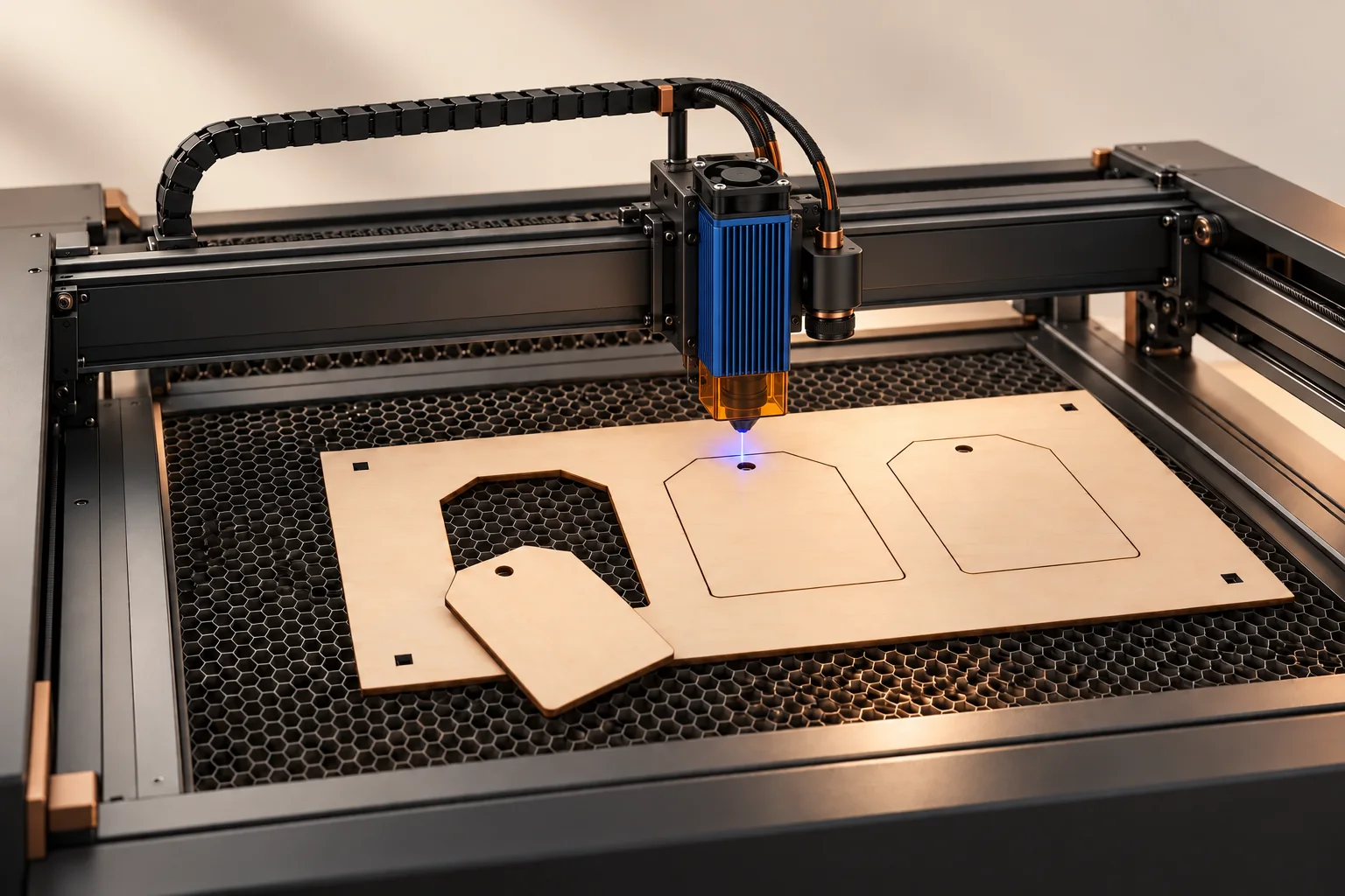 Ideas take shape here.Concept illustration
A simple outline. A new possibility.
Scroll to explore, or select a step. Camera registration · Automatic alignment · Modular tools
The vision layer turns what the camera sees into machine coordinates—removing slow manual alignment from the workflow.
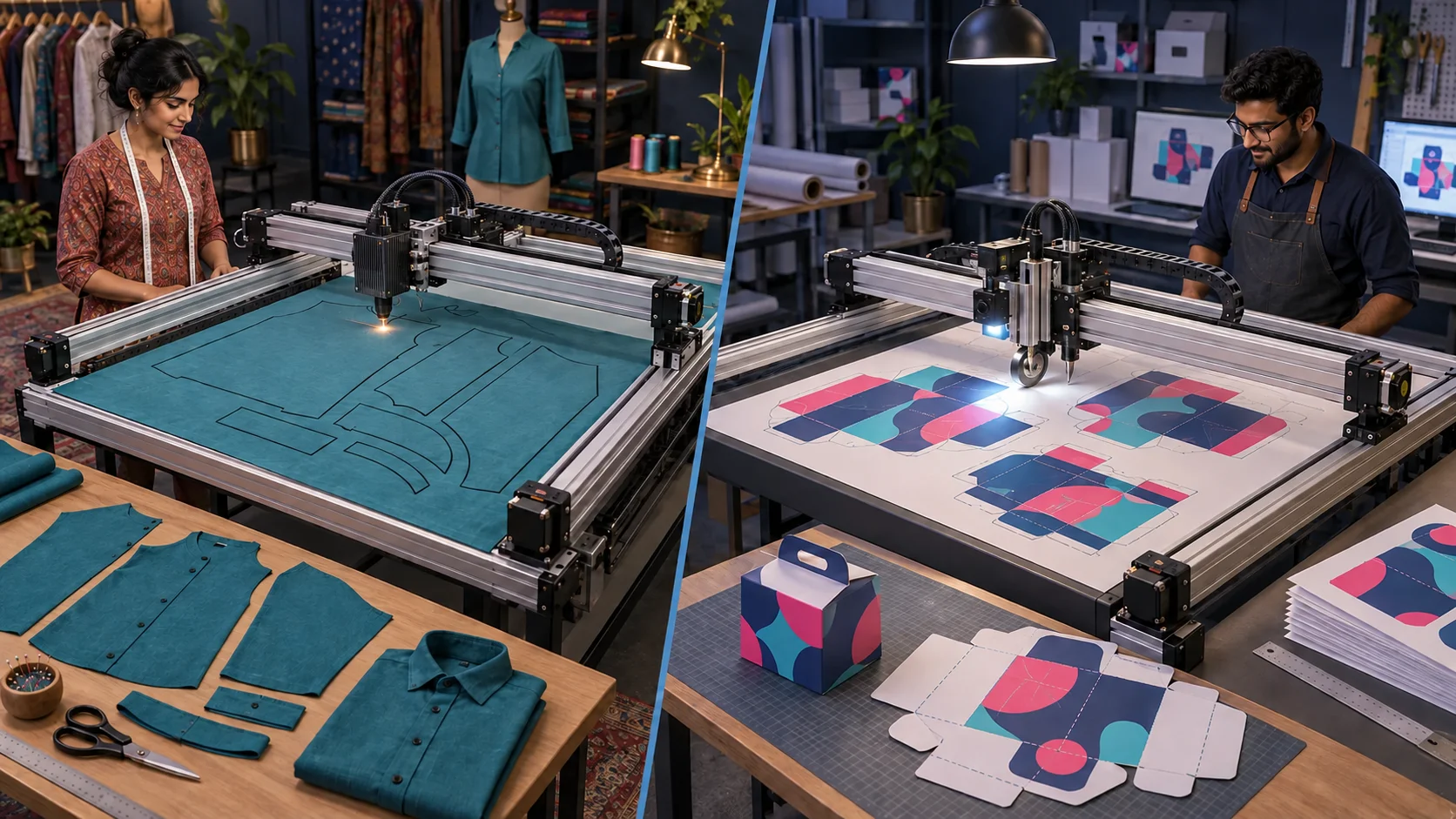
The camera moves with the tool head, capturing the work area to identify registration marks, edges, or the physical pattern placed on it.
Software compensates for translation and rotation, matching the digital cut path to the material as it actually lies.
One coordinated workflow connects capture, detection, correction, and machining.
Calibrated imaging maps the usable bed and workpiece.
Marks, contours, and reference geometry are detected.
The job is translated and rotated into machine space.
The selected head follows the corrected toolpath.
Maps pixels to physical machine coordinates.
Drives the X, Y, and Z axes with limit-aware control.
Scalable frames, beds, and heads fit the application.
Pair vision registration with the head that fits your material and process. Final compatibility depends on the machine configuration.
Align to printed registration marks, score the folds, and cut the contour with tooling matched to your packaging workflow.
Discuss packaging Concept illustration. Tool compatibility depends on configuration.The right head for the work ahead.

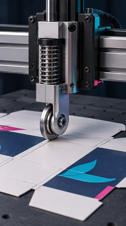
Score fold lines on printed card and packaging blanks. Direction encoders guide wheel orientation.
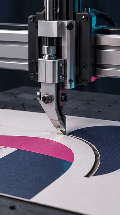
Cut shaped contours in printed card and other suitable sheet materials with a tangential knife and direction encoders.
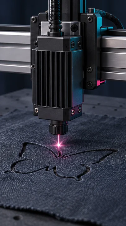
Cut custom shapes with an optional laser head assembly.

Draw line art, patterns, and portraits with a pen mounted on the gantry.
See the plotting example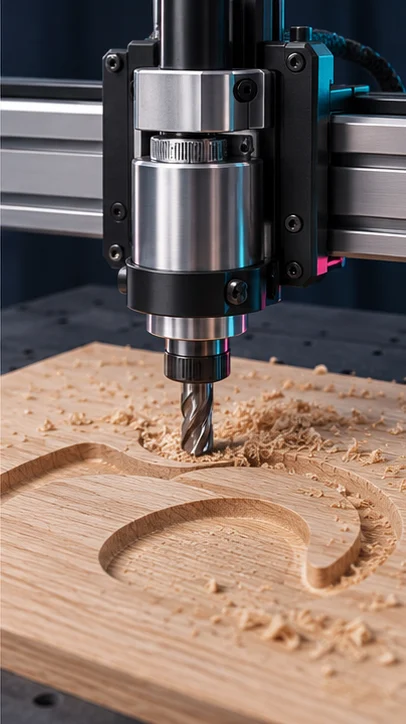
Mill contours and shallow pockets in suitable rigid materials such as wood.
Capture a physical pattern or template with a camera, then trace its shape into editable digital outlines for your design workflow.
From garment pieces to existing templates, bring physical shapes into a digital workspace.
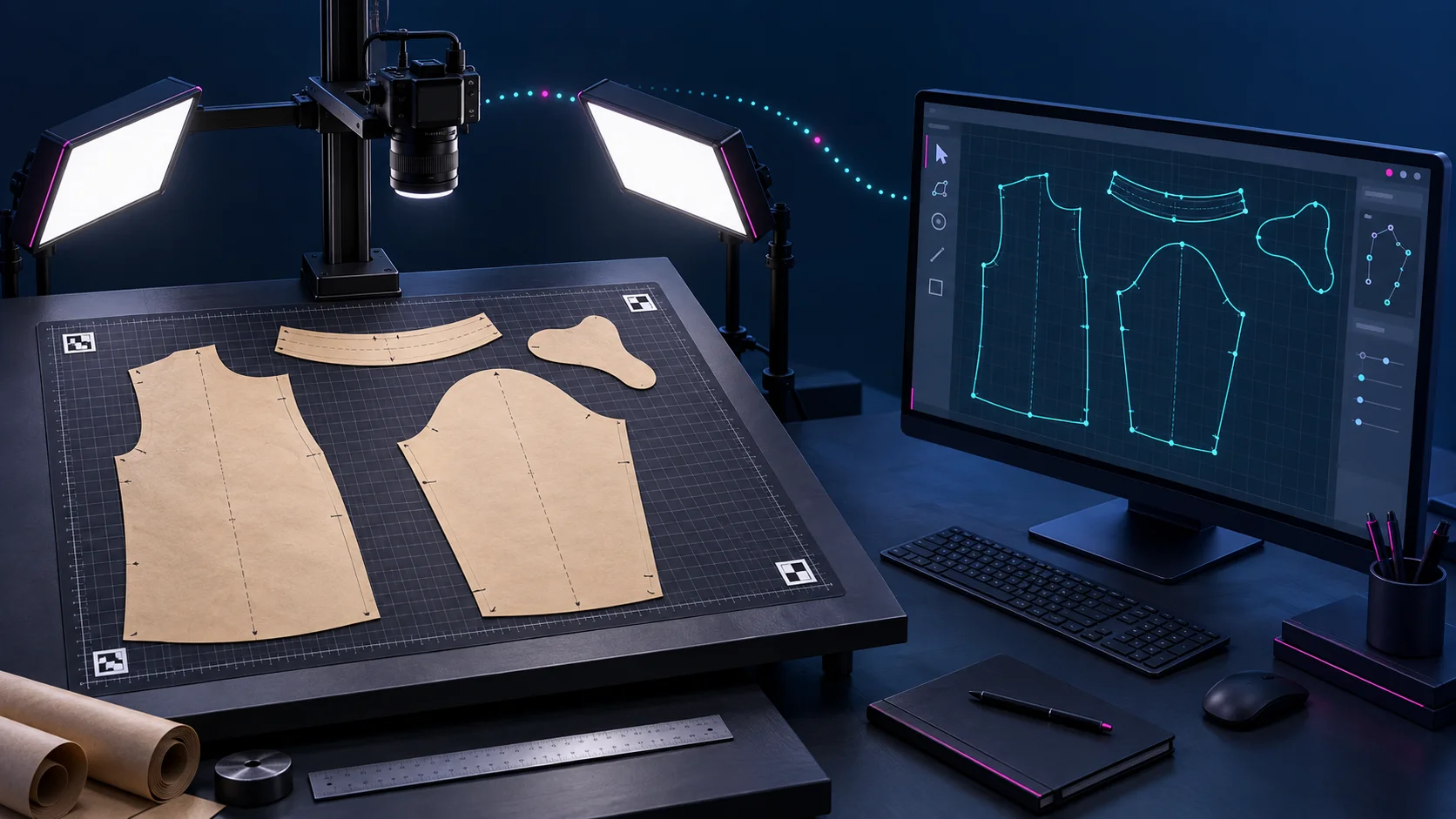
Explore the machine, calibration, vision registration, and creative applications.
Select the X, Y, and Z gantry modules for your setup.
Choose a scalable bed or the scalable honeycomb alternative.
Match the camera, lighting, control module, and tool head to your workflow.
Tell us your application, working area, gantry requirements, and preferred tool heads. We will help you configure your CNC build.
Contact us for pricing, module details, and help choosing your configuration.
We are based in Chennai, serving customers across India.
